Gaote Holding Group focuses on the research and development and production of various valves


-
Products

-
-
-
I. Core Structural Features (with illustrations)
- Flange connection design :The valve body uses National standard flange connection (Compliant with GB/T 9119, Plane and raised face integral steel pipe flanges), the flange sealing surface and bolt hole layout are compatible with the national standard pipeline system, ensuring connection sealing and engineering versatility.
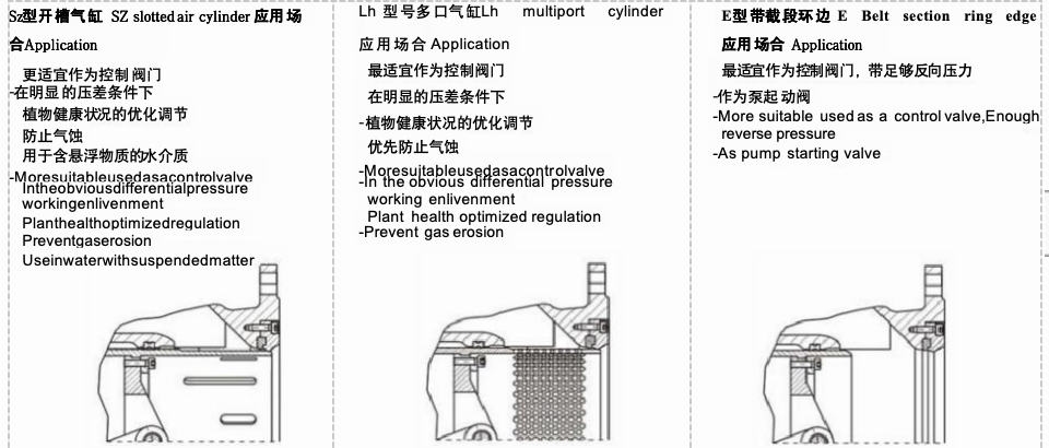
- Piston adjustment component :Internal configuration Piston adjustment structure (The image shows the annular piston component inside the valve body), the flow area is changed by the axial displacement of the piston to achieve precise flow regulation; the sealing surface uses Soft and hard combined sealing design (Compliant with GB/T 12238 General valves, flange and butt weld gate valves sealing requirements), ensuring zero leakage of the medium during adjustment.
- Dual drive control mechanism :Configuration Handwheel manual adjustment (Black handwheel on the left side of the image) and Electric actuator (Blue device), the electric actuator complies with GB/T 28270 Technical conditions for electric devices, supporting manual/electric dual-mode operation, suitable for automated control scenarios.
- Valve body material and process :The valve body is made of ductile iron (QT450-10) casting (implementing GB/T 12227 General valves, technical conditions for carbon steel castings), the surface is treated with anti-corrosion spray coating, pressure-resistant and impact-resistant, suitable for municipal, industrial and other complex working conditions.
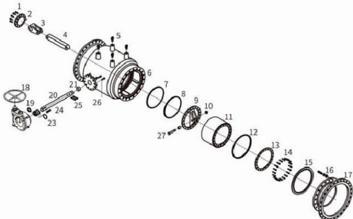
Parts material table Parts Material
Serial number No .
Ser NO
|
Parts Name
Parts Name
|
Serial number No.
Ser NO
|
Parts Name
Parts Name
|
Serial number No. Ser NO
|
Parts Name
Parts Name
|
1
|
Conductor bonnet bolt
|
10
|
Piston sleeve connected pin cap
Piston sleeve connected pin cap
|
19
|
V-oil seal sleeve sleeve
|
2
|
Conductor bonnet Conductor bonnet |
11
|
Piston sleeve
|
20
|
Shaft Shaft |
3
|
Drive shaft seat seat
|
12
|
Seal Ring
|
21
|
Bearing segment segment |
4
|
Drive pole
|
13
|
Seal ring clamp
|
22
|
Gearbox
|
5
|
Cliver Cliver |
14
|
Seal ring clamp bolt mp bolt
|
23
|
O-ring
|
6
|
Valve body Body
|
15
|
Seat Seat |
24
|
4-sides keyboard |
7
|
Piston sleeve sealing ring Piston sleeve s ealing rin g
|
16
|
Short pipe fixing bolt and gasket
Short pipe fixing bolt cap and gasket
|
25
|
Drive shaft seat pin seat pin
|
8
|
Piston sleeve sealing ring Piston sleeve s ealing rin g
|
17
|
Outlet short pipe Outlet short pipe |
26
|
Gearbox fixing bolt
|
9
|
Piston sleeve seat
|
18
|
Hand wheelb
|
27
|
Piston sleeve connected pin
Piston sleeve connected pin
|
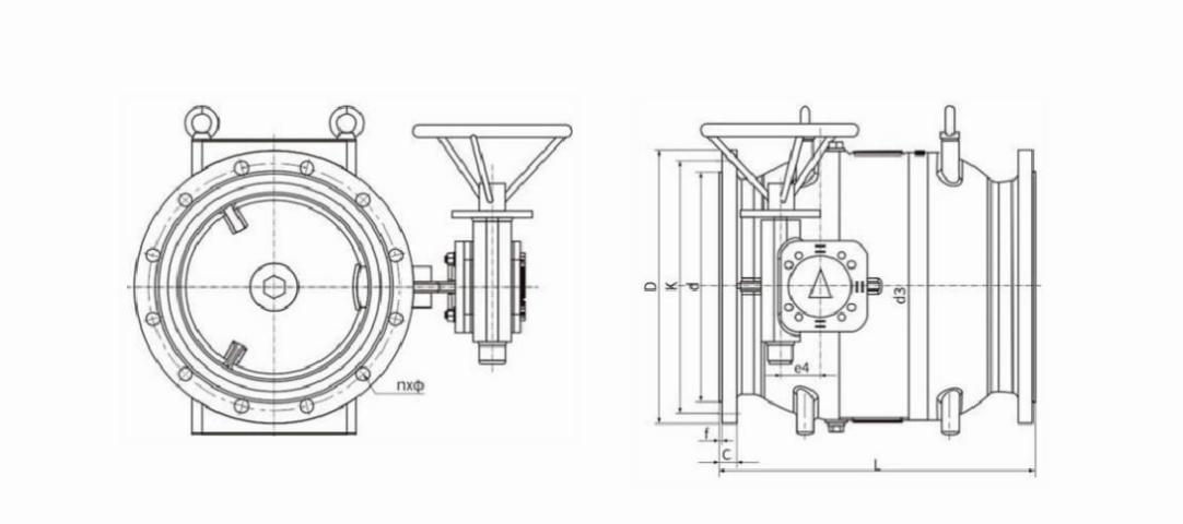
Main external dimensions connection dimensions(mm) external dimensi ons and connection dimensions(mm)
DN
|
L |
D |
K |
d |
C |
f |
n×φ
|
|||||
PN10
|
PN16
|
PN10
|
PN16
|
PN10
|
PN16
|
PN10
|
PN16
|
PN10
|
PN16
|
|||
200
|
400
|
340
|
340
|
295
|
295
|
266
|
266
|
20
|
20
|
3
|
8×23
|
12×23
|
250
|
500
|
395
|
405
|
350
|
355
|
319
|
319
|
22
|
22
|
3
|
12×23
|
12×28
|
300
|
600
|
445
|
460
|
400
|
410
|
370
|
370
|
24.5
|
24.5
|
4
|
12×23
|
12×28
|
400
|
800
|
565
|
580
|
515
|
525
|
480
|
480
|
24.5
|
28
|
4
|
16×28
|
16×31
|
450
|
900
|
615
|
640
|
565
|
585
|
530
|
548
|
25.5
|
30
|
4
|
20×28
|
20×31
|
500
|
1000
|
670
|
715
|
620
|
650
|
582
|
609
|
26.5
|
31.5
|
4
|
20×28
|
20×34
|
600
|
1200
|
780
|
840
|
725
|
770
|
682
|
720
|
30
|
36
|
5
|
20×31
|
20×37
|
700
|
1400
|
895
|
910
|
840
|
840
|
794
|
794
|
32.5
|
39.5
|
5
|
24×31
|
24×37
|
800
|
1600
|
1015
|
1025
|
950
|
950
|
901
|
901
|
35
|
43
|
5
|
24×34
|
24×40
|
900
|
1800
|
1115
|
1125
|
1050
|
1050
|
1001
|
1001
|
37.5
|
46.5
|
5
|
28×34
|
28×40
|
1000
|
2000
|
1230
|
1255
|
1160
|
1170
|
1112
|
1112
|
40
|
50
|
5
|
28×37
|
28×43
|
1200
|
2400
|
1455
|
1485
|
1380
|
1390
|
1328
|
1328
|
45
|
57
|
5
|
32×40
|
32×49
|
1600
|
3000
|
1915
|
1930
|
1820
|
1820
|
1750
|
1750
|
49
|
65
|
5
|
40×49
|
40×56
|
Keyword
Piston type flow control valve
Professional valve manufacturing
Contact Us
Belongs to:


Gaote Holding Group Co., Ltd.
Tel: +86-595-8896-8800
Email: gaotegroup@126.com
Address: Chenggong Development Zone, Ximei Street, Nan'an City, Quanzhou City, Fujian Province


Leave a message
* Note: Please be sure to fill in the information accurately and keep the communication open.